Stop Losing Geometry Data When Moving DXF Files Into Excel
Stop Losing Geometry Data When Moving DXF Files Into Excel
If you work in engineering, architecture, or surveying, you know the frustration of needing precise measurements from a CAD drawing but only having access to spreadsheet software. You need those coordinates for cost estimation, inventory tracking, or structural analysis. However, opening a DXF file directly in Excel often results in garbled text or missing data points entirely.
The standard copy and paste method fails because vector graphics do not translate linearly into grid cells without specific parsing logic. This disconnect forces professionals to waste hours manually typing values that should be automated instantly. The result is inconsistent datasets, calculation errors downstream, and wasted billable time on administrative tasks instead of actual engineering work.
This article explains why this data loss occurs during the transfer process from CAD formats to spreadsheets. We will explore three real-world scenarios where accurate coordinate extraction matters most. Finally, we provide a step-by-step solution using specialized tools that handle binary vector parsing better than native Excel functions ever could.





The Technical Reason Why DXF Data Fails in Excel Cells
To understand the failure point, you must look at how computers store drawing information versus spreadsheet data. A Microsoft Excel file is fundamentally a grid-based database where every cell holds a specific value or formula reference. It expects rows and columns to align perfectly.
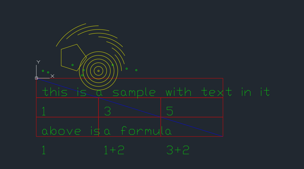
In contrast, a DXF (Drawing Exchange Format) file stores vector geometry using mathematical definitions of lines, arcs, circles, and polylines in 2D or 3D space. These objects are defined by start points, end points, radii, centers, and layer properties rather than fixed grid positions.
When you attempt to open a DXF file directly inside Excel without an intermediary parser, the application tries to interpret binary vector commands as text strings. This leads to several specific issues:
- Misaligned Coordinates: The X and Y values often get split across different cells or merged into single unreadable blocks.
- Scaled Units Mismatch: CAD files frequently use millimeters while Excel defaults assume inches, leading to massive calculation errors if not converted during import.
- Layer Data Loss: Critical metadata about which object belongs to a specific layer (like electrical vs. plumbing) is stripped away because the spreadsheet has no concept of drawing layers.
This structural incompatibility means that manual entry becomes necessary unless you use software designed specifically for this translation task. Native Excel features like Power Query can handle CSV imports, but they cannot parse raw DXF vector structures without external drivers or specialized add-ins to bridge the gap between geometric data and tabular rows.
Three Real-World Scenarios Requiring Accurate Data Extraction
The need for this specific workflow is not theoretical. Professionals encounter these hurdles daily when integrating design files with financial or operational spreadsheets. Here are three common use cases where precision matters.
- Floor Plan Cost Estimation: A construction manager needs to calculate the total linear footage of piping required for a new building. The architect provides a DXF floor plan with pipe runs drawn as polylines. Manually measuring each segment in CAD and typing it into an Excel budget sheet is prone to human error. If one line is missed, the material order will be short.
- Circuit Board Verification: Electronics engineers often need to verify component placement against a Bill of Materials (BOM). The PCB layout exists as DXF layers showing pad locations. They must extract X and Y coordinates for every solder point to ensure the automated assembly machine is programmed correctly.
- Surveyor Boundary Analysis: Land surveyors work with boundary lines defined by latitudes, longitudes, or local grid systems. They need these points in Excel to calculate land area using specific formulas like the Shoelace formula. If the coordinate data is corrupted during transfer, the calculated acreage will be incorrect.
In each scenario, the cost of error exceeds the time saved by manual entry. A single decimal point shift can result in ordering wrong materials or building structures out of alignment with legal boundaries.
Step-by-Step Solution for Reliable DXF to Excel Conversion

The most reliable method to solve this problem involves using dedicated software that understands the DXF file structure and exports it into clean CSV or Excel formats. While you can attempt complex VBA scripts, they often break when encountering different CAD versions or proprietary object types.
Step 1: Prepare Your Source File
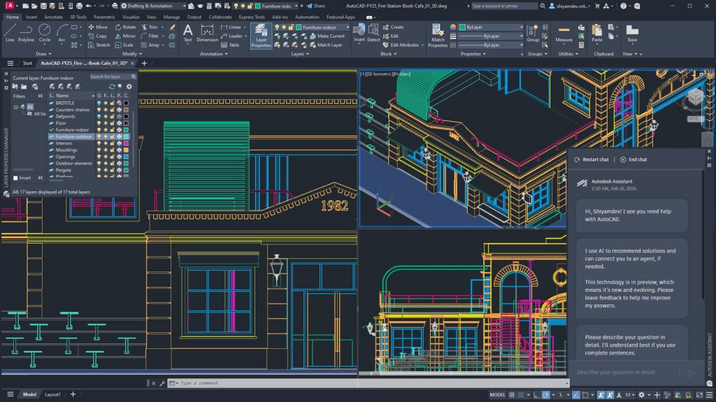
Before importing anything, ensure your source DXF file is cleaned up in AutoCAD or similar software. Remove unnecessary blocks that do not contain geometric data you need to extract. Purge unused layers and linetypes if possible.
Step 2: Utilize Specialized Parsing Tools
Rather than building this from scratch, DXF Reader GT provides a direct solution. This tool reads the binary vector data and converts it into tabular XYZ values that Excel can understand immediately.
- Select Your File: Open DXF Reader GT and browse to your specific drawing file location.
- Choose Export Format: Select CSV or XLSX as the output format. This ensures compatibility with standard Excel formulas without needing further conversion steps.
- Filter Layers (Optional): If you only need data from a specific layer, such as “Walls” or “Pipes”, use the tool’s filtering options to exclude irrelevant geometry before export.
Step 3: Import into Excel
Once exported, open your spreadsheet. You will see columns typically labeled X, Y, Z (if applicable), Layer Name, and Object Type. This structure allows you to use standard functions like SUMIFS or VLOOKUP immediately.
An Advanced Variation: Visualizing the Extracted Data
If your goal is not just calculation but visualization of spatial data within Excel itself, there are further steps available after extraction. Once DXF Reader GT has exported your XYZ coordinates into a clean table, you can feed that same dataset directly into other tools.
For example, if the data represents terrain elevation or surface irregularities extracted from a CAD model, standard Excel charts will struggle to render 3D surfaces accurately. In this specific case, XYZ Mesh can take those exported coordinates and generate an interactive 3D graph directly inside the workbook.
This combination creates a powerful workflow:
- Extract Geometry: Use DXF Reader GT to get raw coordinate points from your CAD file.
- Clean Data: Remove outliers or noise using standard Excel filtering.
- Visualize Surface: Load the cleaned XYZ data into XYZ Mesh for a 3D surface plot that allows you to inspect peaks and valleys without leaving Excel.
This approach bridges the gap between engineering design files and executive reporting dashboards. It eliminates the need to maintain two separate software environments (CAD for viewing, Spreadsheet for analysis) by bringing both capabilities into one file.
Common Mistakes or Misconceptions About DXF Imports
Even with tools available, users often encounter issues due to incorrect assumptions about how CAD data translates. Here are the most frequent errors that lead to inaccurate results.
Mistake 1: Ignoring Scale Factors
CAD drawings can be created in millimeters while your budget spreadsheet expects feet or meters. If you do not apply a scale factor during import, every calculated length will be off by orders of magnitude. Always verify the unit setting on both the source file and the target export settings.
Mistake 2: Assuming All Objects Are Lines
A DXF file contains circles, arcs, splines, and text objects in addition to lines. A simple line extraction script will ignore these shapes entirely or treat them as single points depending on the parser logic. Ensure your tool supports exporting endpoints for all object types you require.
Mistake 3: Overlooking Coordinate Systems
Different CAD files may use different origin points (0,0). One file might be centered at a building corner while another uses global survey coordinates. If you merge data from multiple DXF files without normalizing the coordinate system first, your combined dataset will show objects in completely wrong locations relative to each other.
Mistake 4: Relying on VBA for Binary Parsing
Many users attempt to write a Visual Basic macro that opens a DXF file as text and parses the lines manually. This is fragile because modern DXF files are often binary or use complex group codes that simple string splitting cannot handle reliably.
VBA Alternative: When Manual Parsing Is Necessary
If you must automate this process without external tools, VBA offers a limited workaround for text-based DXF versions. However, it requires strict error handling and is not recommended for complex drawings with thousands of objects due to performance lag.
Sub ImportSimpleDXFText()
    Dim fso As Object, ts As Object
    Dim lineText As String

    ' Create File System Object
    Set fso = CreateObject("Scripting.FileSystemObject")

    ' Open the text version of DXF file (requires conversion first)
    On Error Resume Next
    Set ts = fso.OpenTextFile("C:\Data\Drawing.dxf", 1, False, -2)
    If Err.Number  0 Then Exit Sub

    Dim rowCounter As Integer
    rowCounter = 1

    ' Loop through lines looking for coordinate codes (simplified example)
    Do While Not ts.AtEndOfStream
        lineText = ts.ReadLine

        ' Check if this is a vertex point code in DXF structure
        If InStr(lineText, "VERTEX") > 0 Then
            Cells(rowCounter, 1).Value = "Point Data"
            rowCounter = rowCounter + 1
        End If
    Loop

    ts.Close
End Sub
The code above demonstrates the fragility of manual parsing. It only works if you have already converted your DXF to a readable text format and know exactly where vertex data appears in that specific file version. A specialized tool handles these variations automatically.
Brief Technical Conclusion
Moving geometry from CAD drawings into Excel spreadsheets is not as simple as opening the file directly. The fundamental difference between vector graphics and grid-based databases causes significant data loss if standard methods are used without proper parsing logic.
The most robust solution combines manual verification with specialized software like DXF Reader GT. This ensures that coordinate precision is maintained, units are converted correctly, and layer metadata remains intact. For users who need to visualize this data further after extraction, tools such as XYZ Mesh provide the necessary bridge for 3D surface plotting within Excel.
By automating the translation process rather than relying on manual entry or fragile scripts, you eliminate calculation errors caused by bad imports and save significant time during project estimation phases. This workflow allows engineering teams to focus on design integrity while letting software handle the tedious task of data migration between incompatible file formats.